English
 Español
 Português
 Français
 Русский язык
 Italiano
 Deutsch
 Nederlands
 لعربية
 한국어
한국어 Japanese
 ภาษาไทย
 Türkçe
 Tiếng Việt
 Bahasa Indonesia
 Hindi
Hindi kazakh
 Uzbek
Uzbek Thai
Thai Farsi
Farsi
LCD Splicing Screen Matrix Selection Matching Guide
 2026-08-17
 1505
1505




2026-08-17
1505
Signal Switching, Hardware Matching and Wiring Setup For Display Projects
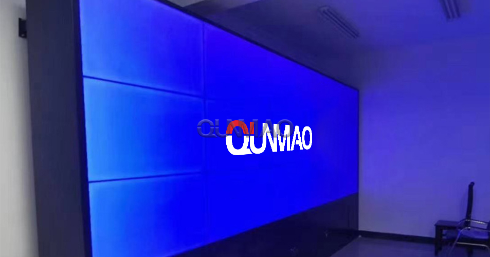
Qunmao Display Technology Co., Ltd. designs and manufactures LCD splicing screens for real‑world deployment. These large‑format display units find heavy use inside government offices, shopping malls, corporate lobbies and monitoring centers. Many project buyers and installers understand panel specifications well. They stay unclear about supporting hardware such as the splicing matrix. This article walks you through matrix selection, matching rules and core roles within a full display system.
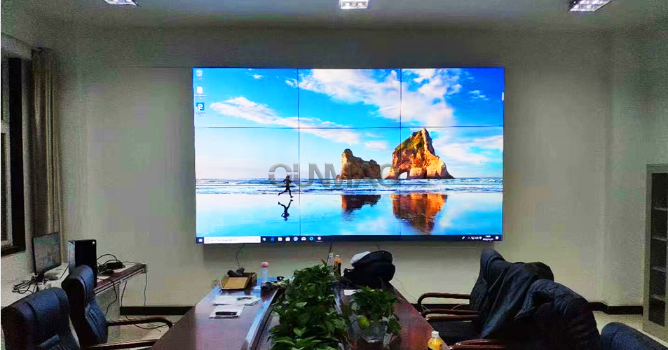
A splicing screen matrix belongs to dedicated hardware built for multi‑panel splicing projects. It acts as both signal processor and video switcher inside your whole display setup. You feed multiple signal sources into its input ports. The matrix routes these signals toward different output channels linked to your splicing panels.
You can switch between sources without swapping physical cables. One camera feed may show across the whole video wall. Another PC signal may split and occupy only several panels. This hardware gives you flexible signal management for large‑screen installations. It sits at the signal core between your source devices and the physical LCD wall.
People classify matrix hardware mainly by supported signal interfaces. Each interface carries different resolution limits and transmission distances. You pick interfaces based on your existing source equipment and cable layout on‑site.
HDMI matrix: Handles modern high‑definition digital video. Works for PC, set‑top box and 4K signal sources. Widely used in meeting‑room and exhibition‑hall projects.
DVI matrix: Pure digital video transmission. Common for older high‑resolution industrial display deployments.
VGA matrix: Analog signal type. You will meet this type in legacy equipment with no digital output available.
BNC matrix: Suited for analog camera monitoring signals. Popular within security monitoring room projects.
SDI matrix: Delivers stable long‑distance transmission. Mainly used for broadcast‑grade video equipment.
Mixed‑signal matrix: Combines multiple interface types inside one unit. Fits sites with mixed old and new signal devices.
Many buyers over‑spec matrix hardware. They select higher port counts than their project actually requires. This adds unnecessary material cost. You follow two simple counting rules for port planning.
The total number of matrix output ports needs to be greater than or equal to your physical splicing panel count. Each panel requires one dedicated output channel. Input port count needs to cover all signal sources you plan to connect.
Take one practical case for reference. You build a 3×4 splicing wall with 12 physical panels. You feed 10 separate computer signal sources into this system. A 12‑input 12‑output matrix meets your needs. You gain no real‑world benefit paying extra for a 16‑input 16‑output model. You can still leave spare ports for future device expansion if your client has clear upgrade plans.
Count total physical splicing panels first, confirm minimum required output ports.
List every signal source device, confirm minimum required input ports.
Reserve small amount of spare ports only when future equipment expansion is confirmed.
Match matrix interface types to the actual output ports from your signal‑source hardware.
Check resolution and refresh rate specs to match your LCD splicing panel parameters.
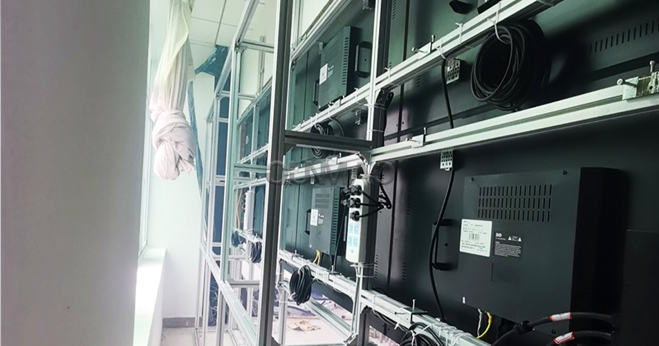
Wrong wiring creates black screens, signal flicker or total system failure. You follow these clear steps during on‑site installation work.
Run cables from each signal‑source output port to corresponding input ports of the matrix unit.
Run cables from matrix output ports to every individual splicing screen panel.
Link all splicing panels in series with RS‑232 control lines. Connect the final panel in this chain to your control computer.
Complete signal compression setting for display devices inside configuration menus.
Launch your splicing processor software, establish communication and send control commands toward the matrix hardware.
RS‑232 serial control handles configuration and switching instructions. Video signal cables carry visual content. Keep control wiring separate from high‑power power cables. This cuts down signal interference during daily operation.
Today’s matrix hardware brings more than basic signal switching. It adds practical control options for operators working on‑site or remotely.
Mobile control support. You send commands via WEB page or APP from Android or iOS tablets and phones.
4K 30Hz input and output capability for high‑definition source material.
Physical visual buttons on the device chassis for quick manual operation without software.
Centralized control capability to work with third‑party room control hosts.
Compliant with HDMI 1.4a protocol, supports Deep Color color processing.
One single signal source can duplicate and display across multiple output displays at the same time.
You do not add a matrix for every single splicing‑screen build. Small fixed‑content projects may run without one. You will see heavy matrix use in these common environments.
Enterprise conference rooms. Multiple notebook and desktop PCs feed content onto the video wall for meetings and presentations.
Security monitoring rooms. Large numbers of camera feeds need fast switching and assignment onto different panel zones.
Exhibition halls. Different demonstration devices push rotating content toward the large display wall.
Government command centers. Mixed signal sources from many departments require unified signal management.
| Evaluation Item | Points You Need To Check | Common Practical Recommendation |
|---|---|---|
| Input Port Quantity | Match total signal‑source count, reserve spare ports for confirmed expansion | Input ≥ actual source device count |
| Output Port Quantity | Must cover total physical splicing panel units | Output ≥ number of splicing screens |
| Signal Interface Type | Match source device output interfaces on‑site | HDMI for modern projects; mixed matrix for legacy‑device sites |
| Resolution Support | Align with splicing panel native resolution | 4K 30Hz for most new commercial projects |
| Control Method | Check RS‑232, WEB, APP and physical button support | Choose units with multiple control paths for operational flexibility |
| Applicable Scene | Conference room, monitoring room, exhibition hall, command center | Single‑interface matrix for simple sites; mixed‑signal matrix for complex multi‑source sites |
| Cost Risk | Avoid buying excessive port quantities you will never use | Calculate ports based on real‑site equipment list before placing orders |
Buy matrix ports far beyond actual project needs, creating unnecessary hardware expense.
Mismatch matrix interface types with source‑device output ports, forcing extra adapter converters.
Ignore RS‑232 wiring requirements. Control software cannot send switching commands to matrix hardware.
Run RS‑232 control cables alongside high‑voltage power cables, triggering signal interference.
Fail to verify matrix resolution limits. High‑definition sources cannot output full quality onto splicing panels.
Skip spare port planning for known future‑add devices, requiring full hardware replacement later.
Q1: Can I run a splicing video wall without installing a matrix?
You can skip matrix hardware for very simple deployments with only one fixed signal source. When you need to switch among multiple input sources or assign different sources to different panel zones, matrix hardware becomes necessary.
Q2: What problems show up when matrix input or output ports count is insufficient?
You cannot connect all your source devices or all display panels. You will need external splitters or replace the whole matrix unit. This brings extra cost and project schedule delays.
Q3: Do I need to buy adapters if matrix interfaces differ from source‑device ports?
You will need signal adapters or converter cables. Frequent conversion steps may reduce signal quality. Better to select a matrix with matching native interfaces at the start of your project.
Q4: Why can my matrix not receive control commands from software?
Check RS‑232 wiring sequence first. Confirm serial port parameters such as baud rate match matrix factory settings. Loose serial connections represent the top cause for this common issue.
Q5: Can one signal source show on several separate groups of splicing panels at once?
Modern matrix hardware supports this function. You route one input signal toward multiple output channels. You achieve multi‑zone display without adding extra signal splitters.
Q6: What transmission distance limits apply for matrix signal cables?
HDMI signal runs stable over short cable lengths. For long‑distance runs, you add signal extenders. Consult hardware documentation for maximum cable length specifications of your selected matrix model.
Q7: How should I choose between mixed‑signal matrix and single‑interface matrix?
Pick mixed‑signal matrix when your site carries many different legacy and modern signal devices. Choose single‑interface matrix for clean, new‑build projects with uniform source‑device output types. This keeps your total hardware cost lower.
Count physical splicing panel quantity, calculate minimum required matrix output ports.
List all signal‑source devices, confirm minimum matrix input port requirements.
Check interface types of source equipment, select matching matrix interface options.
Verify matrix resolution and refresh‑rate specs align with your LCD splicing panels.
Confirm control modes: RS‑232, WEB, APP or physical buttons meet operator usage habits.
Plan RS‑232 serial wiring path, keep away from high‑power power cables.
Reserve limited spare ports only for confirmed future equipment expansion.
Complete full signal switching and zone display test before formal project hand‑over.
Matrix hardware forms the signal core for multi‑source LCD splicing wall projects. Correct port counting, interface matching and on‑site wiring cut down most common operational failures. Qunmao Display provides complete hardware matching suggestions for your splicing‑screen projects. Reach out to us when you need tailored system solutions for your installation site.


 Floor 6, Building A, No. 3, North District, Shangxue Science and Technology City, Xinxue Community, Bantian Street, Longgang District, Shenzhen City
 info@szqunmao.com
 +86 15920011166
 +86 15920011166